

PCB assembly guidelines
Special Assembly Requirements
Special Assembly Requirements
Reflow soldering,wave solering and manual soldering are consider as standard PCB assembly,but many projects require special assembly processes in addition to the regular placement-soldering-testing workflow. GWT offers many different options for special assembly requirements, but these must be evaluated on a case-by-case basis during the quoting stages of a project. Clients with such requirements should budget for additional time in both the quoting stage and the PCB assembly stage of the overall turnaround, as well as additional cost.
Special assembly requirements are often very particular to each project, but the following subsections offer some general discussion around the most common types. PCB designers should use this information to develop clear and thorough documentation for their special assembly requirements, which can then be included with the PCB Assembly drawing for their projects
1.Mechanical Component Assembly
Mechanical Supports
The solder connections on a PCB provide enough mechanical strength for the parts to withstand any applied stresses in a majority of projects, but certain applications require additional support for long-term durability. Perhaps the finished product will be subject to vibrational stresses, or it will be repeatedly connected and disconnected from peripheral devices as a part of its operation. In these instances, the recommended best practice is to add mechanical restraints, such as brackets or mounting clamps, around connectors and larger components to affix them in place.
GWT can often provide post-soldering board-level assembly for these types of parts, but the additional cost and lead time requirements must be evaluated on a case-by-case basis during the project’s quoting stage. Clients should be sure to include detailed drawings showing measurements with the quote submission package, mentioning these special requirements as early as possible to their account manager with GWT.
Under certain conditions, components such as voltage regulators or high-speed processor ICs will dissipate considerable amounts of power and may require some additional thermal management. From GWT’s perspective, these requirements are quite similar to the mechanical supports mentioned in the previous subsection in that they require additional board-level assembly either before or after soldering is completed.
Clients should include any heat sink devices required by their project in the associated Bill of Materials when it is sent for quotation and mention this requirement to their account manager with GWT. Detailed drawings showing measurements and orientation should also be included for ease of assembly. Simple heat sinks can often be treated as just one more standard PCB component for quoting purposes, but more complex parts will often require assessment on a case-by-case basis.
2.Adhesives
Epoxies
As mentioned above in Section 3.8.1, the recommended best practice for adding mechanical strength to a component is to use mechanical restraints; however, certain projects will include physical restrictions that prohibit the use of such restraints. In this case, an alternative solution is to use adhesive compounds underneath the part in question. Mechanical restraints are generally recommended over adhesives due to their superior long-term durability, but adhesives do still provide some added support over solder connections alone.
GWT is able to apply heat-cure epoxies underneath connectors prior to the soldering process to satisfy this requirement, but post-soldering underfill for BGAs and other large IC packages is currently not offered.Clients requiring epoxy to be applied under certain connectors should mention this requirement to their account manager during the quoting stage so that GWT’s production team can approve the relevant epoxy and account for any additional cost or lead time requirements as soon as possible.
Tapes
In certain cases, it is necessary to apply pressure sensitive adhesive tapes to certain components or sections of a PCB. These tapes are used in many applications: sometimes to protect against short circuits with the PCB’s external environment, and in other cases to affix the entire PCB to an external heat sink or mounting bracket. GWT frequently uses 3M9077 adhesive in such cases due to its strong dielectric properties and high temperature tolerance, up to 260°C.
Clients requiring adhesive tapes to be applied after PCB assembly should mention this requirement to their account manager during the quoting stage of the project. A detailed masking drawing, showing specific measurements, should be included with the initial quote package submission to allow sufficient time for GWT’s production team to approve the requirement.
3.Pressfit Parts
Pressfit parts, mainly used for interconnection of different electronic assemblies, are often large components incorporating multiple rows of pins. G W T can handle assembly for pressfit connectors, but usually will require additional tooling cost, which must be evaluated on a case-by-case basis during the quoting stage of the project. GWT can handle tolerances of ± 3 mil preferred or ± 2 mil minimum for pressfit part hole location;there will likely be some extra cost involved to control down to ± 2 mil.
Clients whose designs include pressfit parts should mention this to their account manager with GWT, and also include the parts themselves in the project’s Bill of Materials.
4.Wire Bonding
GWT offers a selective soft gold surface finish option, which can be applied to specific areas or specific pads on a board during the PCB Fabrication process to facilitate wire bonding. This allows for a stronger welded joint on the pad in question, which offers increased durability for leads soldered directly to the PCB. This process requires a masking drawing to specify the regions for soft gold finish, as well as additional documentation to describe the wire bonding procedure, and might not be viable for volume orders. Generally, it is more cost and time-effective to use connectors and terminated cables for interconnection, but wire bonding might be necessary for size-restricted designs that are unable to incorporate these larger parts.
For projects that specify wire bonding, please include a masking drawing for selective soft gold finish along with the standard quote package and mention this requirement to a GWT account manager. GWT’s production team will need to assess each wire bonding project individually for potential additional cost and lead time.
5.Wire Harness
Wire harness assembly, also known as cable harness assembly or simply wire assembly / cable assembly, is generally performed after the regular board-level PCB assembly process. GWT is focused mainly on board-level services, but wire harness assembly is also available in certain cases. For high-volume or very complex wire harness assembly, many of GWT’s clients work with a separate final assembler to bring the populated PCBs into the finished end product. That being said, GWT can certainly handle assembly for many straightforward and lower-volume wire harnesses.
Clients requiring wire harness assembly should provide a detailed drawing including measurements along with their standard quotation package. Wires themselves, as well as any connectors or crimps, will need to be included on the project’s Bill of Materials as well. GWT’s production team evaluates wire harness assembly jobs on a case-by-case basis to provide quotation on any additional labour cost and lead time, and in some cases additional tooling cost must be added to build a fixture or purchase crimping tools.
Clients should mention any wire harness assembly requirements to their account manager with GWT as early as possible in the quoting process to ensure timely assessment and quotation.
6.Enclosure Assembly
Once the PCBs for a given project are fabricated and assembled, the final step is often to enclose the PCB in a box for end use. injection molding or other forms of custom enclosure manufacturing are offered, but GWT can provide enclosure assembly with lower-volume final assembly and high-volume complex enclosure assembly.
Clients requiring enclosure assembly should provide a detailed drawing including measurements along with their standard quotation package. For projects incorporating a commercially-available prefabricated box, the associated part number and description should be included on the project’s Bill of Materials; custom boxes manufactured by a third party should be included as consigned parts.
GWT’s production team evaluates enclosure assembly jobs on a case-by-case basis to provide quotation on any additional labour cost and lead time, so it is advisable to mention any enclosure assembly requirements to a GWT account manager as early in the quotation process as possible.
7.Conformal Coating
For PCBs that will be used in damp, humid, dusty, or other harsh environments, a special process known as conformal coating is often required. Through this process, GWT will cover the assembled PCB in a thin layer of non-conductive, protective material such as silicon, acrylic, urethane, or paraxylene. Once this coating is cured onto the board, it will increase the overall durability of the product while also protecting it from outside contaminants.
Clients should submit a masking drawing along with standard design files to stipulate any areas of the board that should not be subjected to the coating, such as connectors that will need to be accessed at a later time. The conformal coating process does require additional time and cost after PCB assembly, and GWT also requires that functional testing (see Section 3.10.3) be performed on assembled PCBs prior to coating. Once the coating has been applied, the boards are fully sealed, and rework can no longer be performed.
8.IC Programming
GWT offers two types of IC programming for embedded systems PCBs, which can be added to a PCB assembly quotation upon client request. For either method, a hex file should be submitted with the standard quotation package, along with a brief procedural explanation for any requirements in terms of settings, configurations, or checksums. GWT understands the importance of intellectual property protection and will readily sign on to a mutual non-disclosure agreement before receiving any design files. Strict quality management systems guarantee an efficient and effective programming service for either of GWT’s programming methods.
Normally, direct-chip programming is the preferred method, both from GWT’s point of view and from the client’s point of view. This process uses the SP-5000 universal programmer in conjunction with independent socket adaptors to program IC packages prior to assembly, meaning the design of the PCB does not need to offer access to the programming interfaces. This method is also more time effective during production, particularly for higher-volume orders
Alternatively, GWT can offer In-Circuit Serial Programming (ISCP) services, where the programming is done after the PCBs have been fully assembled. This method usually requires more cost and lead time compared with direct-chip programming since the PCBs must be powered and connected one-by-one to a computer for programming. This method is normally used only for very low-volume prototype designs so that clients can modify the code during their own test procedures.
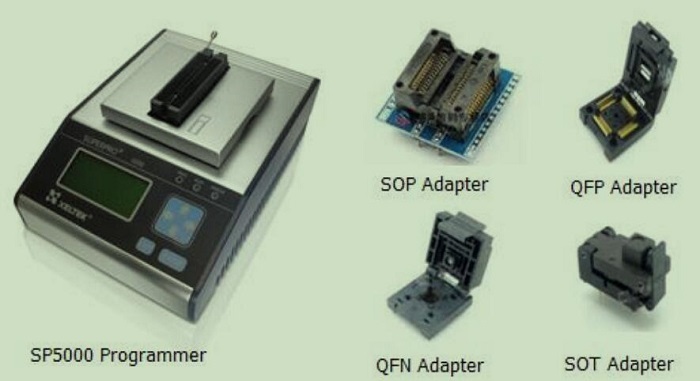
Figure 01-Some of GWT's Direct-Chip Programming Equipment
9.Serialization
Clients often design serial numbers onto the silkscreen of their PCBs, which falls into the realm of PCB fabrication rather than assembly; this process is discussed in GWT’s DFM Guidelines document. That being said, some clients prefer to use labels for serialization, either due to space restrictions on the PCB silkscreen layer or simply for aesthetic reasons. Clients requiring this service need only mention it to their GWT account manager during the quoting stage of the project.
Serialized labels are added after the PCB assembly process is done, normally on the bottom of the boards, or in any open space where they will not interfere with components. Barcodes can also be included on the labels to ease shipping and receiving for GWT’s clients on higher-volume orders, but it should be noted that barcode labels will require some additional cost to be added to the project. Simple serial number labels can be applied at no additional charge.
10.Flux and Solder Types
GWT uses a high-quality no-clean flux during assembly, which normally leaves the boards free of residue. If any significant flux deposits are noticed during visual inspection, they will be cleaned off before the PCBs are packaged for shipping; this is usually only necessary for through-hole components.
Water soluble flux is also available for special order. There is no additional cost or lead time involved, but clients requiring water soluble flux should inform their GWT account manager early in the quote stage of the project.
Being a fully RoHS-compliant facility, GWT only uses lead-free solder in PCB assembly; specifically, SAC305 is GWT’s material of choice. This solder is composed of 96.5% tin, 3% silver, and 0.5% copper.
0users like this.
